Pipeline
Created: March 14, 2025 8:33 PM Tags: Computer Hardware
IEM - instruction Execution Machine 0.2
each instruction goes 1 each stage per cycle,
each stage take 1 clock cycle, so single instruction executes 6 cycles
only 1 instruction is executing at any time
example: what is CPI in this design:
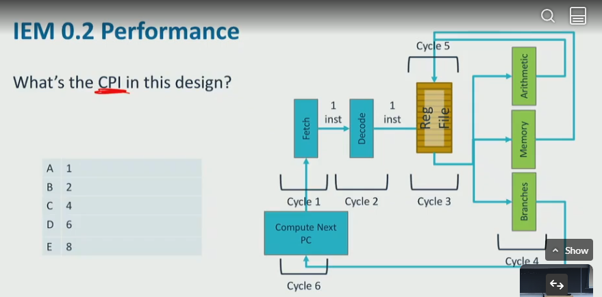
- the CPI is 6, the cycles: fetch → decode → RF read → execution/memory → RF write → update PC
pipeline CPU
- the CPU pipeline alllows each cycle to handle different instruction in order, so concurrently we can execute 6 instruction in order, just like assembly line
- however, it is NOT impacting performance,
- pipelined CPI: 1 (from 0.2 reduce from 6)
- cycles to execute a single instruction remains roughly constant
- required:
- CPU initiate new instruction each cycle
- CPU completes an instruction in each cycle
hazards
- when processor dont have something needs to process instruction
-
control hazards: fetch stage does not know which instruction to fetch
A hazard that occurs when the pipeline needs to determine the correct instruction to fetch after a branch, or ran into pipeline stall (bubble)
pipeline stall: A temporary delay in the pipeline execution flow (e.g., due to control hazards), where no new instructions are issued in some cycles
- possible causes:
- ran into a loop
- if statement checks for unlikely error conditions
- unconditional branches
- solution: speculative execution,
- processor guess (speculate) which branch will go
- no more hazards
- how to guess?
- guess backward branch? (since loop goes backwards)
- cached prediction
-
create a map with key = 00,01,10,10, value is boolean (default false)
key was_last_branch_taken 00 true 01 false - suppose at branch predictor, we want to predict if program will go to addr- take the first 2 bits of addr, and look up at the table. ifwas_last_branch_taken == true, predict to goto that branch- on UPDATE PC stage, get the prediction result and update the table - how to rollback if guess is wrong - processor squashes it when branch resolves - discard/rollback/suppress register/memory updates - called flushing the pipeline - CPU flushes
-
IEM 0.6
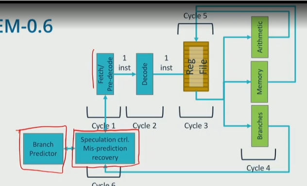
- a branch detector is used to make predictions based on prior branch outcomes
- fetch: predecode and predict next PC
- update PC: detect mispredictions
- Update PC stage must correct if wrong, misprediciton recovery
-
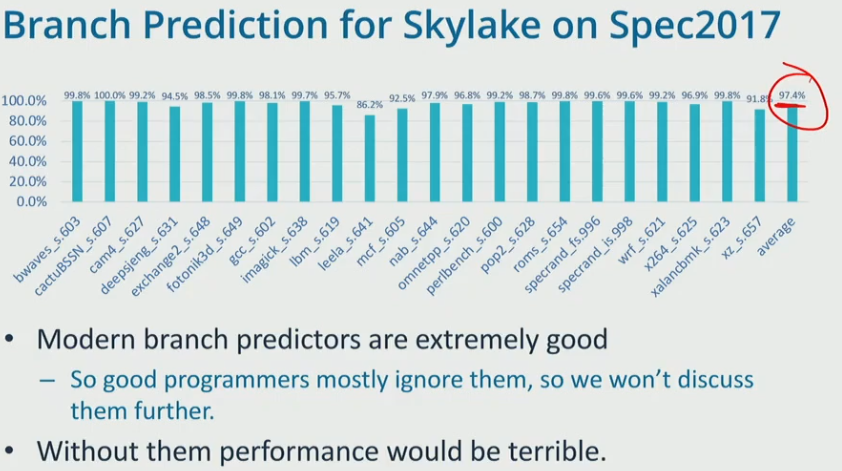
modern predictors:
- use bigger table
- dont change prediction after one misinterpretation
- account for history of branch behavior, and global pattern of branch behavior…
- possible causes:
-
data hazards: execution stage does not have operand it requires
A situation where an instruction depends on the result of a previous instruction that has not yet completed.
- for example, if we have the following instruction:
```c
addl %esi, %edi //fetch @ 1, write to register file @ 5
addl %edx, %edi //fetch @ 2, needs to read from RF @ 4, but its not available
```
IEM - 0.8
- x86 pipelines DONT actually execute x86 instructions, they translate x86 instruction set into micro-ops or uOps (IEM-0.8)
- CPI = 1, CT = low, supports x86
- uOps are simple,
- small number of arithematic ops
- 0 or 1 mem access
- 0-2 reads, 0-1 write
IEM 1.0
- CPI < 1 means more than 1 instruction finishes executing per cycle
- execute instructions ASAP using instruction level paralleism
- processor utilize ILP using out of order execution (OOO)
- OOO solve several problems at once
- reduce CPI
- handles data depencies, long-latency instructions
- OOO concepts
- register dependencies
- register renaming
- OOO issue
example: which pair of uOPs can execute in reverse order?
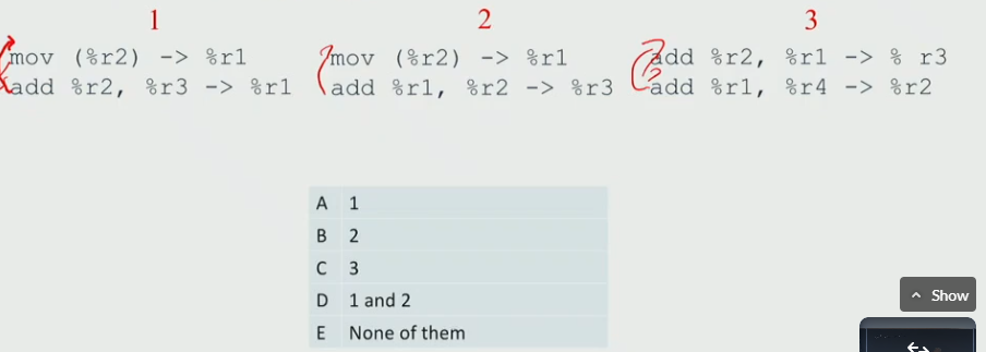
- E
data dependencies
-
it constrain the order of instruction
- read-after-write (RAW)
- True dependency
- we want processor only constrained by True dependency (RAW)
-
write-after-write (WAW)
- False dependecy
- when both instruction write to the same register
- we can make them write to different register, so we can perform OOO
-
write-after-read (WAR)
- false dependency
- similalry, we can write to different registers to perform OOO
- read-after-write (RAW)
dependencies and dataflow graphs
- (a) They do not include branches. ❌
- False. Dependence graphs can include branches since branches affect control dependencies.
- (b) Nodes represent instructions. ✅
- True. In a dependence graph, each node corresponds to an instruction in the program.
- (c) Fewer edges in the graph generally means more ILP. ✅
- True. Fewer dependencies allow more instructions to execute in parallel, increasing Instruction-Level Parallelism (ILP).
- (d) The edges include memory and register values. . ❌
- False. Edges represent dependencies, including both register and memory dependencies (RAW, WAR, WAW), but not values
- (e) Only the compiler can construct a dependence graph. ❌
- False. The hardware (e.g., Tomasulo’s algorithm, dynamic schedulers) and compilers can both construct and use dependence graphs.
- (f) The critical path through the graph sets the minimum number of cycles it takes to execute the instructions. ✅
- True. The longest dependency chain (critical path) determines the minimum execution time in cycles.
- (g) Edges represent a requirement that one instruction execute before another. ✅
- True. Edges denote data dependencies (RAW), anti-dependencies (WAR), and output dependencies (WAW) that constrain instruction execution order.
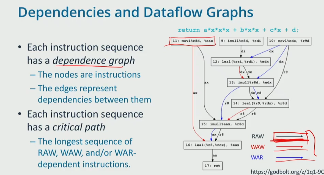
- dependency graph
- critical path is the longest path, assume every node take 1 cycle
- the length of critical path is 7, 9→ 12 → 13 → 14 → 15 → 16 → 17
-
the average CPI for the dataflow graph is
\[ CPI = \frac{\text{critical path number of cycles}}{\text{number of instructions}} \] -
therefore, CPI = 7 / 9
instruction level parallelism (ILP)
- exists when multiple instructions can be executed at the same time
- instructions per cycle (IPC) = 1 / CPI
- the x86 does not have many registers to use, therefore, we need to
- rename some of the architecture register to physical registers to use
register alias table (RAT)
- rename the architectural registers (r9, di, si) to physical registers (pr19, does not actually exist)
- architectural registers:
- A register explicitly defined by the ISA and visible to the programmer through the instruction set.
- physical registers:
- A register in the CPU that stores instruction results, including uncommitted ones.
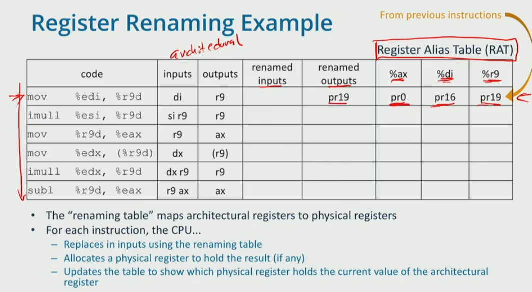
- r9 is renamed to pr19, read from the table,
diis mapped topr16. therefore: - suppose we rename the output to
pr20, sor9is update topr20. look up latest di and r9 before this row from the table.dimaps topr16, andr9maps topr19 - suppose renam the output to
pr21, it mapsaxtopr21 -
….
Code Inputs Outputs Renamed Inputs Renamed Outputs %ax %di %r9 mov %edi, %r9ddir9pr16pr19pr0 pr16 pr19 imull %esi, %r9d di r9r9pr16 pr19pr20pr20 mov %r9d, %eaxr9 ax pr20pr21pr21mov %edx, %r9d dx r9 pr3pr22pr22 imull %edx, %r9d dx r9 r9pr3pr22pr23pr23 subl %r9d, %eax r9 ax ax pr23pr21pr24pr24 -
therefore, we simply the datagraph:
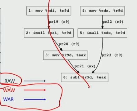
- now it length of critical path = 4, CPI = 4/6, ILP = 6/4
example:
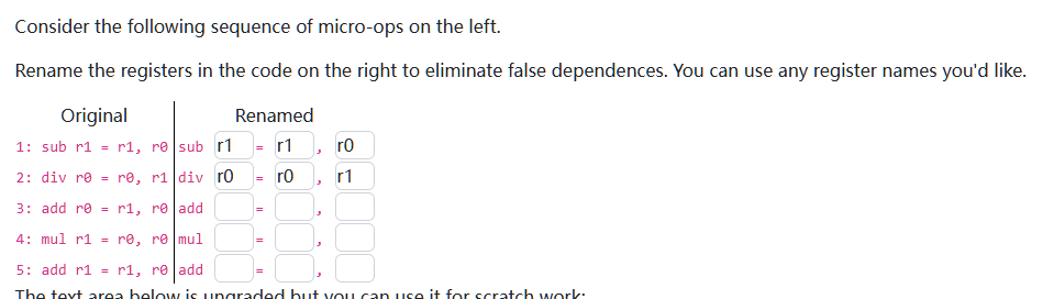
| code | inputs | output | rename input | rename output | %r0 | %r1 |
|---|---|---|---|---|---|---|
sub r1 = r1,r0 |
r1, r0 | r1 | r1, r0 | r2 | r2 | |
div r0 = r0, r1 |
r0, r1 | r0 | r0, r2 | r3 | r3 | |
add r0 = r1,r0 |
r1, r0 | r0 | r2,r3 | r4 | r4 | |
mul r1 = r0,r0 |
r0 | r1 | r4 | r5 | r5 | |
add r1 = r1, r0 |
r1, r0 | r1 | r5, r4 | r6 | r6 |
exploit ILP
reorder buffer (ROB)
- CPU fetches many instructions keeps them in a reorder buffer
- each cycle CPU selects instructions with no remaining dependencies and exec them
- since it can execute multiple instructions, CPI can be < 1
Tomasulo’s Algorithm
enables out-of-order execution by allowing instructions to execute as soon as their operands become available.
Reservation Stations: Each instruction (uOp) is assigned a reservation station, which holds necessary operands and waits for execution.
- Issuing Instructions:
- Instructions can issue when all input operands are available.
- If operands are missing, they are fetched from either:
- The physical register file before entering the scheduler.
- Broadcasted by an ALU (arthematic logic unit) after a previous instruction completes.
- Execution Readiness: The table lists reservation stations and shows whether each instruction is ready to issue.
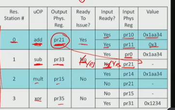
- Reservation Station #0 (add) is ready to issue because:
- All input operands (pr10 and pr11) are available.
- It will broadcast pr21’s value (0x1aa34) after execution.
- Station #1 (sub) is waiting on pr21 from station #0.
- Station #2 (mult) is also waiting on pr21.
- Station #3 (xor) is waiting on pr31, which is not available.
execution:
- Station #0 issues and completes execution.
- It broadcasts pr21 = 0x1aa34.
- Stations #1 and #2 receive pr21’s value and become ready to issue.
modern IEMs
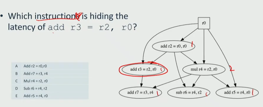
Effective instruction Latency
It is the time an instruction adds to the critical path, considering dependencies.
example:
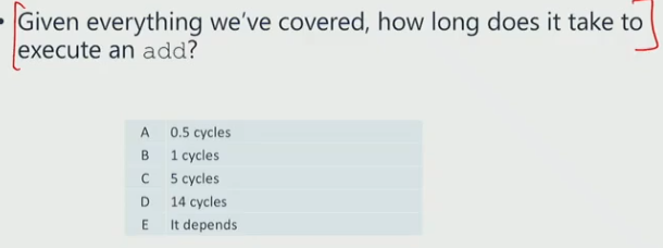
- 1 cycle
- if it is not in the critical path, then the effective latency is 0
- if on CP, then latency is how many cycles it adds
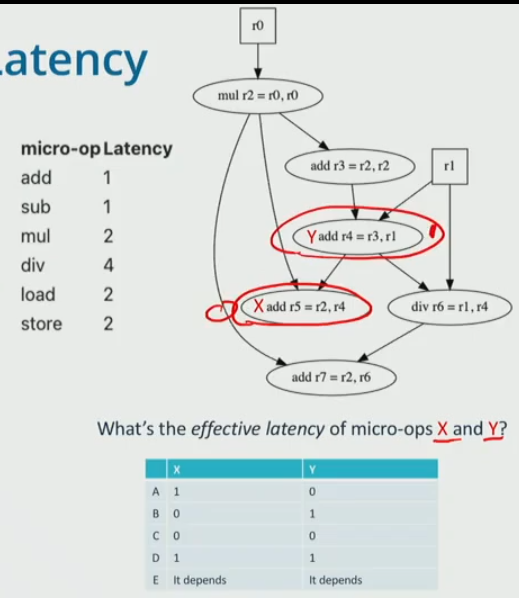
- the CP is mul → add r3 → add r4 → div → add r7
- x is not in the critical path, therefore mem latency is 0
- y is in the critical path, therefore mem latency is 1
effective memory latency
- long, at least 4 cycles, 100s of cycles max
- cache miss often on CP
latency hiding
(b)Parallel execution helps hide latency by allowing multiple instructions to proceed simultaneously.
(c)It helps reduce the visible impact of instruction or memory latency by keeping the processor busy.
Out of order execution allows the pipeline to hide the latency of some instructions.
when there are 2 memory loads, one of them is hided from the CP
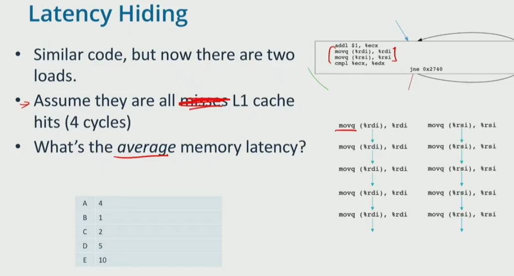
-
- the number of cycles is 4 * 5 = 20, the number of instructions is 10, therefore, average memroy latency is 20 / 10 = 2
- what happen if the right all cache misses (
movq (%rsi), %rsi) and take 12 cycles per load?- we call the misses hides the latency of hits, the hits are free
- C, the CP is 4 cycles, it hides the path
example: find the max speedup
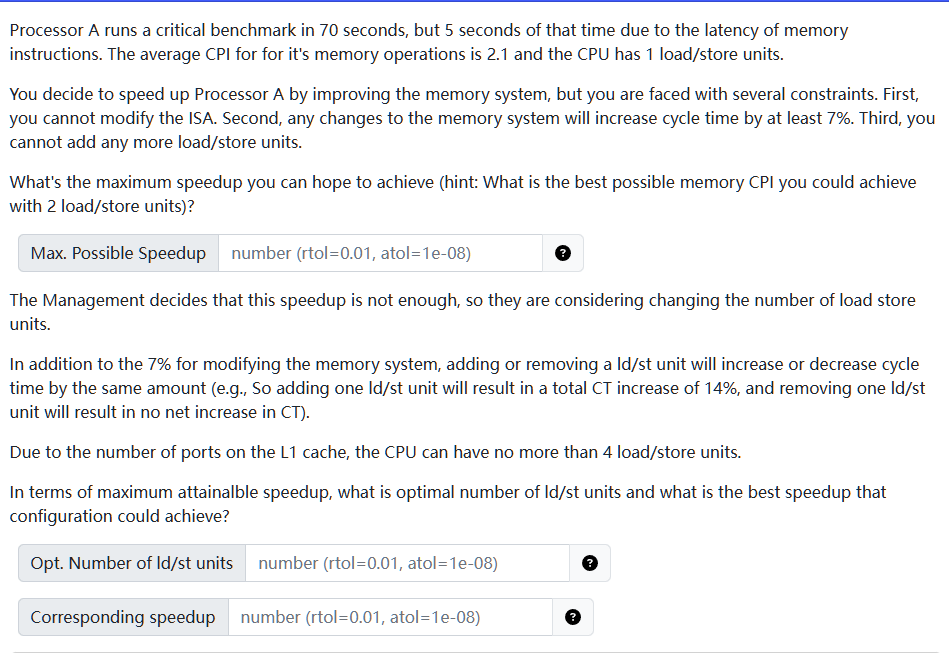
- we can speed up memory CPI to 1 cycle at max, so
- improved memory time: 5 / 2.1 = 2.38
- new total time = (2.38 + 65) * 1.07 = 72.096
- the speed up = 70 / 72.096 = 0.9709
- we already shown that even under the most optimal memory time, it would worsen the total execution time. since no matter how many load/store units we have we can never reach the optimal CPI, we can never get a better speed up.
- therefore, opt # is 1, and speed up = 0,97
1. fetch
- retrieve instruction forom memory using program counter (PC)
- predict next PC
2. decode
- examine instruction and determine what it does
- decompose instructions in to uOPs
- enqueue resulting Uops in the decode queue
3. RF read
- the register operands for the instruction
- dequeue an uOp from the decode queue, and read register Operands for the instruction
4. execution/memory
- perform Uops arithematic operations and loads/stores
5. RF write
- update the register file
6. compute next PC — update PC
- if instruction is a branch, set PC according to outcome
- if not, increment PC to point to next instruction
- going back to fetch
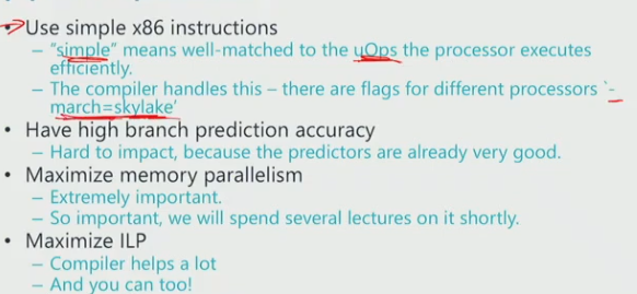
problems with x86 instructional set
- The amount of work per instruction varies.
- Variable length instructions make it hard to know where the next instruction starts.